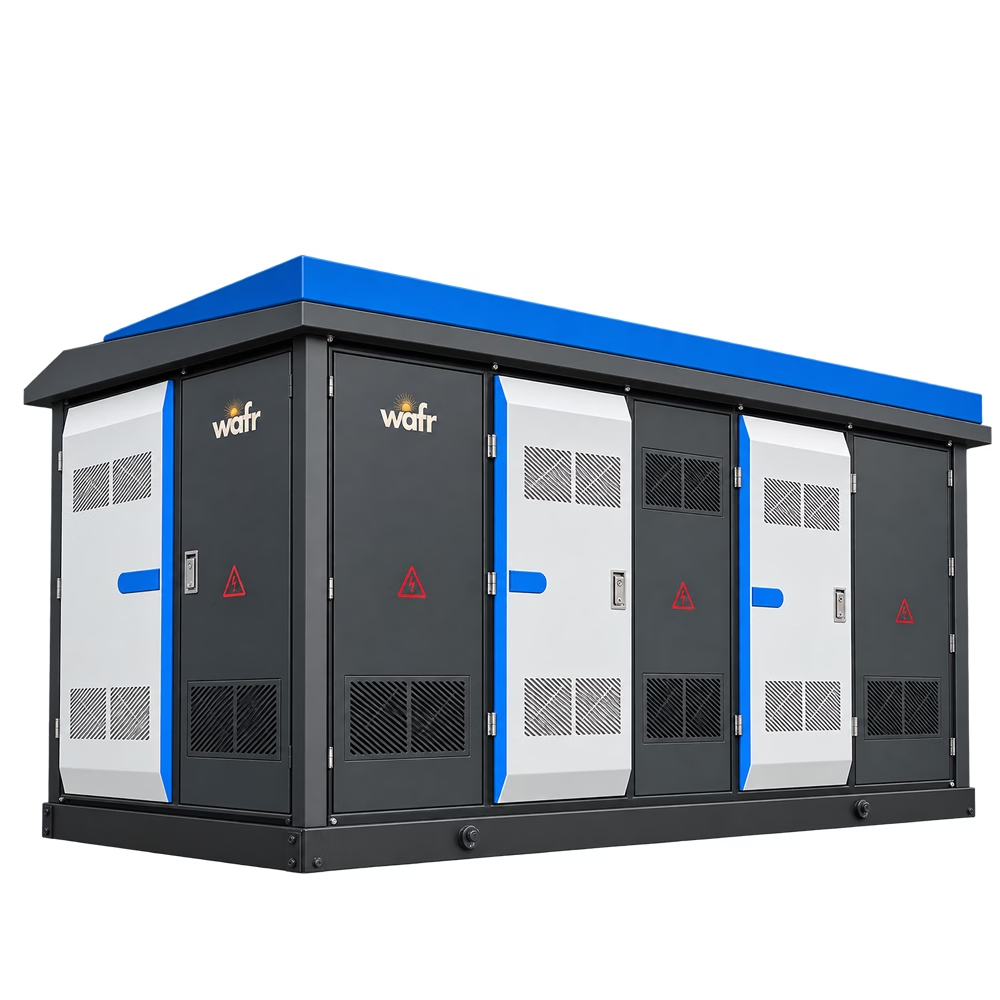
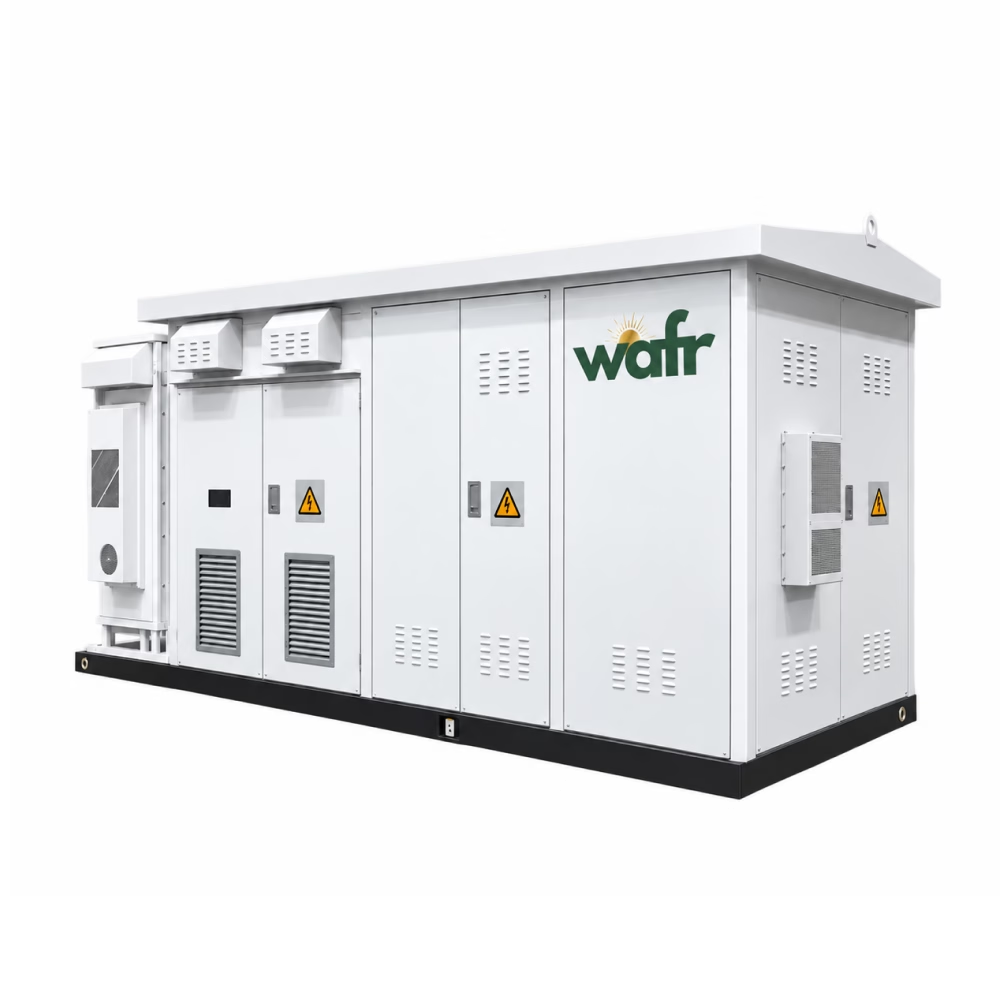
PRODUCT PREVIEW
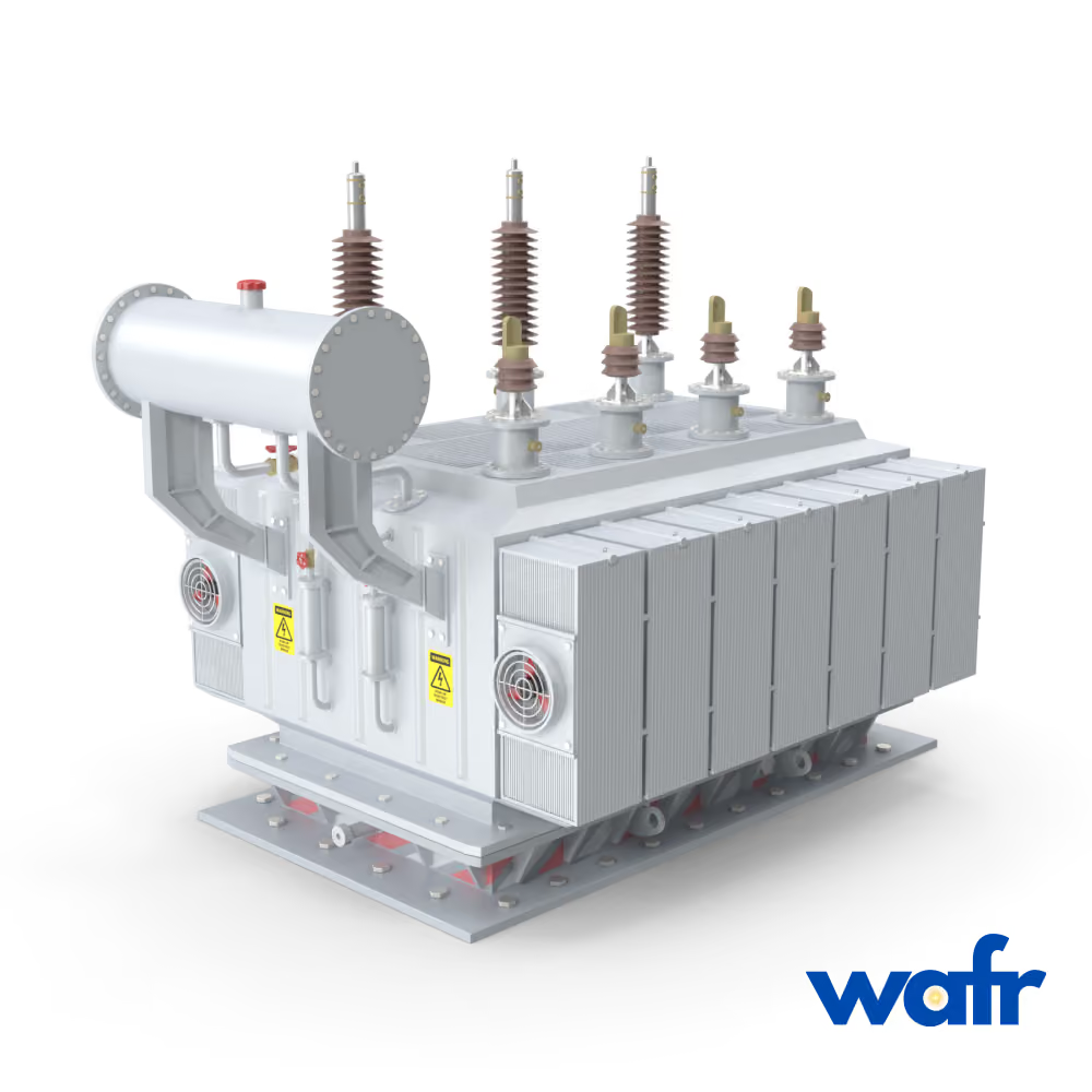
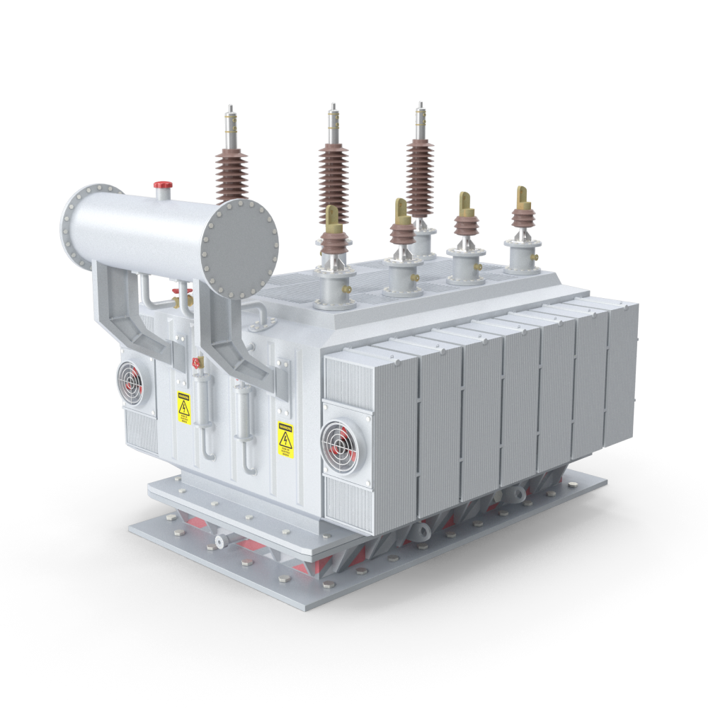
Transformers
Project-specific power transformation
https://cdn.prod.website-files.com/6a838ff6d7b603ad9aeaed44/6aa2f5b6b319e9dc0ddb4863_wafr_transformer_composited_hero_v2.mp4
Wafr Equipment
Under Development
Distribution, power and special-purpose transformers for utility, industrial, mining, data-centre, renewable-energy and critical-infrastructure applications.
Overview
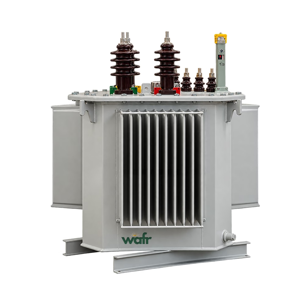
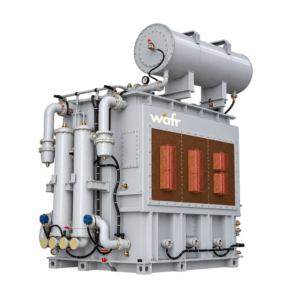
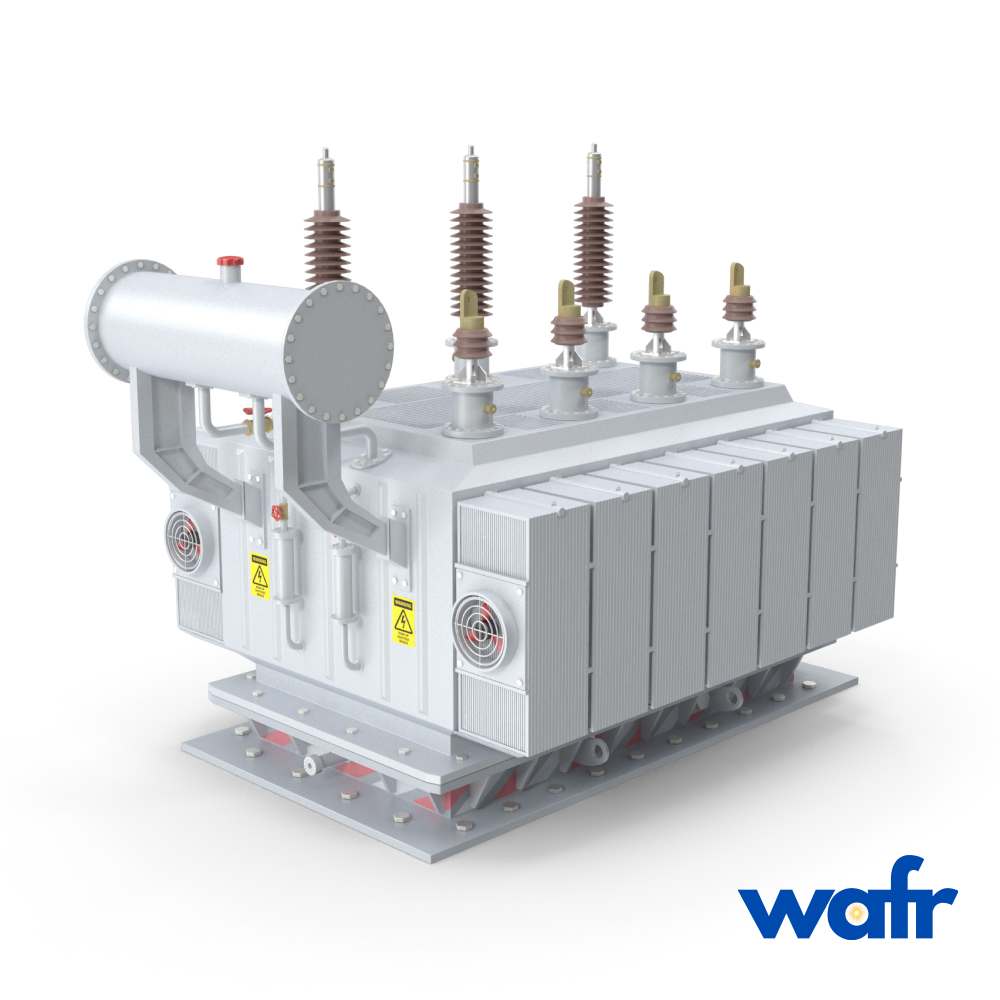
Wafr Technologies provides distribution, power and special-purpose transformers engineered for utility, industrial, mining, data-centre, renewable-energy, commercial and critical-infrastructure applications. Our transformer portfolio covers applications from small single-phase distribution transformers through large substation power transformers, with configurations available for common Canadian distribution and transmission voltages.
Wafr transformer solutions are engineered, manufactured, tested and certified in accordance with applicable CSA, IEEE, ANSI and Canadian energy-efficiency requirements. Available technologies include liquid-filled, pad-mounted, pole-mounted, dry-type, cast-coil, substation power, renewable-energy and custom-engineered transformers.
https://cdn.prod.website-files.com/6a838ff6d7b603ad9aeaed44/6aa2f5b38e85fade4302aa18_electrical-distribution-v2.mp4
Six transformer families, from single-phase distribution through substation power and custom-engineered transformers.
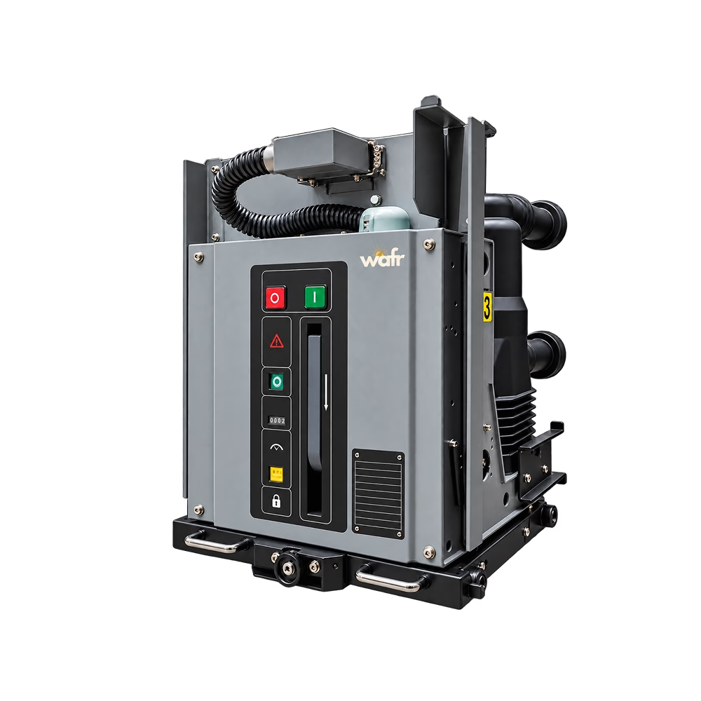
Five switchgear platforms engineered for Wafr's project scope.
Engineering
Wafr's transformer portfolio covers small single-phase distribution transformers through large substation power transformers, configured for common Canadian distribution and transmission voltages.
Structured so engineering and procurement teams can review key ranges quickly.
Liquid-Filled Distribution
45–3,000 kVA · 4.16–34.5 kV · natural ester fluid
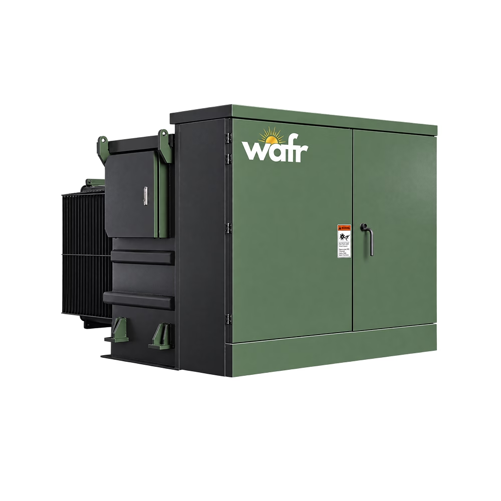
Three-Phase Pad-Mounted
75 kVA–10 MVA · up to 34.5 kV · radial / loop feed
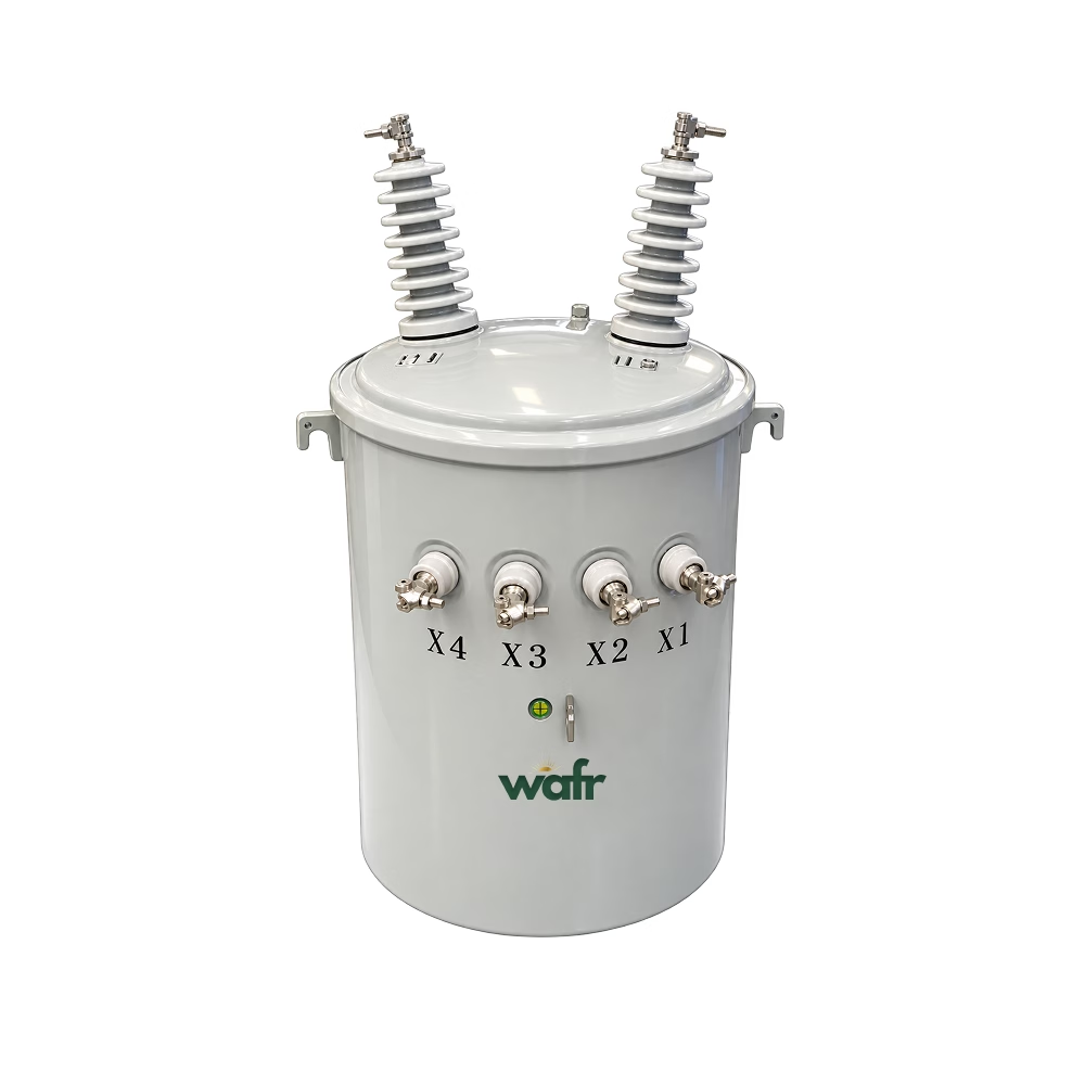
Single-Phase Pole-Mounted
10–167 kVA · 7.2–19.9 kV · 120/240 V secondary
Dry-Type & Cast-Coil
15–7,500 kVA · up to 35 kV · ventilated / VPI / cast-coil
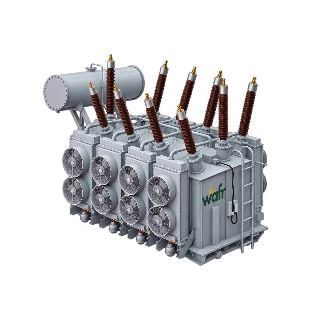
Medium & Large Power
3–200+ MVA · 34.5–230 kV classes · DETC / OLTC
Custom & Special-Purpose
Generator step-up · renewable-energy · special ratios
Frequency
CSA · IEEE · ANSI
Standards
CSA · IEEE · ANSI
Liquid-Filled Distribution
oil-immersed
transformers
Fluid Coolers
fluid-coolers
dry-coolers
WTB Commercial
wtb-commercial
thermal-storage-battery
Three-Phase Pad-Mounted
pad-mount
transformers
Freon Condensers
freon-condensers
dry-coolers
Single-Phase Pole-Mounted
pole-mounted
transformers
Ammonia Condensers
ammonia-condensers
dry-coolers
Dry-Type & Cast-Coil
dry-type
transformers
CO2 Gas Coolers
gas-coolers
dry-coolers
Oil Coolers
oil-coolers
dry-coolers
Medium & Large Power
power-transformers
transformers
Rating Range
HV / LV Voltage
Connection
Cooling
Standard
45–3,000 kVA
4.16–34.5 kV / 600Y/347–208Y/120 V
Delta–Wye grounded
ONAN
CSA C802.1 / IEEE C57.12.00
oil-immersed
15–7,500 kVA
Up to 35 kV / 600Y/347–208Y/120 V
—
AN / AF
CSA C9 / CAN/CSA C802.2
dry-type
10–167 kVA
7.2 / 7.62 / 14.4 / 19.9 kV / 120/240 V
Single-phase
ONAN
CSA C227 series
pole-mounted
750 kVA
12.47 kV / 600Y/347 V
—
ONAN
CSA C227.4 / IEEE C57.12.34
pad-mount
470–2,190 kW
Water / Glycol
1.8–3.2 mm
20 ft (6,058 mm) / 40 ft (12,192 mm)
AC / EC / marine / explosion-proof
fluid-coolers
343–2,005 kW
R404A
1.8–3.2 mm
20 ft (6,058 mm) / 40 ft (12,192 mm)
AC / EC / marine / explosion-proof
freon-condensers
420–2,237 kW
NH3
1.8–3.2 mm
20 ft (6,058 mm) / 40 ft (12,192 mm)
AC / EC / marine / explosion-proof
ammonia-condensers
407–1,267 kW
CO2 (94 Bar)
1.8–3.2 mm
20 ft (6,058 mm) / 40 ft (12,192 mm)
AC / EC / marine / explosion-proof
gas-coolers
240–1,309 kW
ISO VG 46 oil
1.8–3.2 mm
20 ft (6,058 mm) / 40 ft (12,192 mm)
AC / EC / marine / explosion-proof
oil-coolers
Maximum nominal cold storage capacity
kWh(th)
1,500
1,000
500
wtb-commercial
3–200+ MVA
69 kV / 25 kV
Project specific
ONAN / ONAF / OFAF / ODAF
CSA C88 / IEEE C57
power-transformers
1,000 kVA
13.8 kV / 600Y/347 V
—
ONAN
CSA C227.4 / IEEE C57.12.34
pad-mount
3–200+ MVA
69 kV / 13.8 kV
Project specific
ONAN / ONAF / OFAF / ODAF
CSA C88 / IEEE C57
power-transformers
Phase-change temperature
°C
Grade C7: 7.5 ± 1 · Grade C18: 18 ± 1
Grade C7: 7.5 ± 1 · Grade C18: 18 ± 1
Grade C7: 7.5 ± 1 · Grade C18: 18 ± 1
wtb-commercial
1,500 kVA
13.8 kV / 600Y/347 V
—
ONAN
CSA C227.4 / IEEE C57.12.34
pad-mount
3–200+ MVA
115 kV / 34.5 kV
Project specific
ONAN / ONAF / OFAF / ODAF
CSA C88 / IEEE C57
power-transformers
Charging water inlet temperature
°C
C7: 5 · C18: 15
C7: 5 · C18: 15
C7: 5 · C18: 15
wtb-commercial
2,000 kVA
24.9 kV / 600Y/347 V
—
ONAN
CSA C227.4 / IEEE C57.12.34
pad-mount
3–200+ MVA
115 kV / 13.8 kV
Project specific
ONAN / ONAF / OFAF / ODAF
CSA C88 / IEEE C57
power-transformers
Discharge outlet temperature
°C
C7: 7–12 · C18: 18–23
C7: 7–12 · C18: 18–23
C7: 7–12 · C18: 18–23
wtb-commercial
2,500 kVA
24.9 kV / 600Y/347 V
—
ONAN
CSA C227.4 / IEEE C57.12.34
pad-mount
3–200+ MVA
138 kV / 34.5 kV
Project specific
ONAN / ONAF / OFAF / ODAF
CSA C88 / IEEE C57
power-transformers
Peak discharge temperature
°C
C7: 16.8 · C18: per test report
C7: 16.8 · C18: per test report
C7: 16.8 · C18: per test report
wtb-commercial
3,000 kVA
34.5 kV / 600Y/347 V
—
ONAN
CSA C227.4 / IEEE C57.12.34
pad-mount
3–200+ MVA
138 kV / 25 kV
Project specific
ONAN / ONAF / OFAF / ODAF
CSA C88 / IEEE C57
power-transformers
Storage method
—
Latent (phase change)
Latent (phase change)
Latent (phase change)
wtb-commercial
Up to 10 MVA
Project specific
—
ONAN
CSA C227.4 / IEEE C57.12.34
pad-mount
3–200+ MVA
230 kV / 34.5 kV
Project specific
ONAN / ONAF / OFAF / ODAF
CSA C88 / IEEE C57
power-transformers
Rated flow rate
m³/h
58
40
20
wtb-commercial
Water supply pipe diameter
DN
150
150
100
wtb-commercial
Working pressure
MPa
0.8–1.0
0.8–1.0
0.8–1.0
wtb-commercial
Pressure drop
kPa
76.8
65.7
50.7
wtb-commercial
Recommended pipe velocity
m/s
0.8
0.8
0.8
wtb-commercial
Recommended chiller capacity
kW
Per configuration
142–165
70–80
wtb-commercial
Recommended charging window
h
≈ 8 (off-peak / valley tariff)
≈ 8 (off-peak / valley tariff)
≈ 8 (off-peak / valley tariff)
wtb-commercial
Recommended discharge window
—
Local peak tariff hours
Local peak tariff hours
Local peak tariff hours
wtb-commercial
Control
—
Networked automatic program control
Networked automatic program control
Networked automatic program control
wtb-commercial
Unit size (L × W × H)
mm
9,300 × 2,896 × 3,170
6,800 × 2,896 × 3,170
3,808 × 2,896 × 3,170
wtb-commercial
Operating weight
kg
≥ 36,000
≥ 26,500
≥ 14,300
wtb-commercial
Liquid-filled transformers are offered with natural ester insulating fluid for enhanced fire safety, high biodegradability and reduced environmental impact.
Distribution transformers are designed and tested to applicable Canadian energy-efficiency requirements, with high-efficiency and total-ownership-cost optimized configurations available.
Power transformers are engineered around system voltage, MVA rating, impedance, short-circuit requirements, cooling, insulation level, tap-changing and utility specifications.
Non-standard voltage ratios, impedances, cooling arrangements, footprints and environmental requirements can be engineered for specific projects.
Compliance
CSA
Applicable by configuration
UL / cUL
Applicable by configuration
IEEE
Applicable by configuration
ANSI
Applicable by configuration
NEMA
Applicable by configuration
QA Docs
Applicable by configuration
Quality Commitment
24 months warranty against manufacturing defects, counted from commissioning (or 30 months from shipment, whichever ends first)
Covers transformer core, windings, tank and factory-installed components
Defective units repaired or replaced at Wafr's cost, including freight
Technical support: remote diagnosis within 48 hours, on-site service available for major claims
Spare parts shipped within 30 days for standard models
Extended warranty and preventive-maintenance packages available on request
Final warranty terms per purchase contract.
Resources
Everything an engineer or procurement team needs to move from evaluation to specification.
Specify
Transformers
for your project
Send Wafr your project requirements and the team can confirm fit, configuration and documentation.